We are excited to announce the release of GEOtExcel (2025-1), now more accessible, secure, and permanently usable on your personal computer. Based on valuable user feedback, we’ve enhanced the delivery method. GEOtExcel is now available as an Excel-based desktop application, offering the following advantages:
✅ Lifetime, unlimited access on your personal computer
✅ Save, print, and manage data locally, with no restrictions
✅ No internet or cloud connection required
🔺 Important Note: The current version (2025-1) is fully functional and permanently usable on the registered computer. Should future versions be released, existing users will enjoy special discounts for upgrading.
📦 How to Order GEOtExcel – Version 2025
To get started, follow these simple steps:
Download and unzip the provided package: Download here The package contains two Excel files:
File 1: GET ID This file helps you extract your computer’s unique ID. Open it, then click the “Copy Computer ID” button to copy your ID.
File 2: Agreement This file has 3 sheets:
Sheet 1: Price List – Select the GEOtExcel files you wish to purchase; the total price will be automatically calculated.
Sheet 2: Customer & PC Info – Fill in your contact details and paste the copied Computer ID.
Sheet 3: Agreement – Review and sign the agreement.
The “Get ID.exe” file and the GEOtExcel files (which will be shared with you after we receive the completed agreement) are all safe. If your antivirus or firewall issues a warning, please rest assured that the files are secure and can be downloaded and run without concern.
You can be fully confident that our support team will assist you throughout the entire process — including payment, installation, and file delivery. If you have any questions, please feel free to ask. We will guide you through the installation process.
Thank you for choosing GEOtExcel. GEOtExcel Support Team
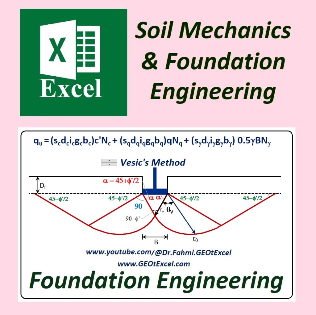
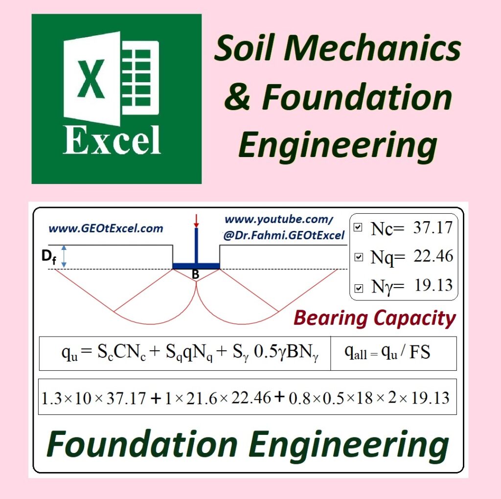
Ultimate Bearing Capacity Calculation (Design) as per IS 6403 Code
Beyond IS 6403: Technical Critique & Recommendations for Bearing Capacity Estimation by GEOtExcel
CODE OF PRACTICE FOR DETERMINATION OF BEARING CAPACITY OF SHALLOW FOUNDATIONS
IS6403 Professional Excel Spreadsheets (GEOtExcel)
1. SCOPE
1.1 This standard covers the procedure for determining the ultimate bearing capacity and allowable bearing pressure of shallow foundations based on shear and allowable settlement criteria.
2. TERMINOLOGY
2.0 For the purpose of this standard, the following definitions shall apply:
2.1 Terms Relating to Bearing Capacity
2.1.1 Net Loading Intensity — The net loading intensity on the foundation is the gross intensity of loading minus the weight of displaced soil above the foundation base.
2.1.2 Ultimate Bearing Capacity — The intensity of loading at the base of the foundation which would cause shear failure of the soil support.
2.1.3 Safe Bearing Capacity — Maximum intensity of loading that the foundation will safely carry without the risk of shear failure of soil irrespective of any settlement that may occur.
2.1.4 Safe Bearing Pressure or Net Soil Pressure for Specified Settlement — The intensity of loading that will cause a permissible settlement or specified settlement of the structure.
2.1.5 Allowable Bearing Capacity — The net intensity of loading which the foundation will carry without undergoing settlement in excess of the permissible value for the structure under consideration but not exceeding net safe bearing capacity.
2.2 General Terms
2.2.1 Density Index (Relative Density) — The ratio of the difference between the void ratios of cohesionless soil in the loosest state and any given state to the difference between its void ratios at the loosest and densest states.
2.2.2 Effective Surcharge at the Base Level of Foundation — The intensity of vertical pressure at the base level of foundation, computed assuming total unit weight for the portion of soil above the water table and submerged unit weight for the portion below the water table.
2.2.3 Footing — A structure constructed in brickwork, masonry or concrete under the base of a wall or column for the purpose of distributing the load over a larger area.
2.2.4 Foundation — That part of a structure which is in direct contact with soil and transmits loads into it.
2.2.5 Shallow Foundation — A foundation whose width is greater than its depth. The shearing resistance of the soil in the sides of the foundation is generally neglected.
3. SYMBOLS
3.1 For the purpose of this code and unless otherwise defined in the text, the following letter symbols shall have the meaning indicated against each:
نماد (Symbol)
(Meaning)
(Unit)
Area of footing
Effective area of footing
Width of strip footing, width of footing, side of square footing, diameter of circular footing
Effective width of footing
Half of B
Cohesion
Undrained cohesion of the top layer
Undrained cohesion of the lower clay layer
Depth of foundation
Depth to water table
d
Depth of top clay layer with undrained cohesion ε1
Depth factors
Eccentricity of loading
Eccentricity of loading along the width
Eccentricity of loading along the length
Horizontal component of loading
Inclination factors
Depth factor (varies linearly from 1 for depth Df=0 to 1.33 for depth Df=B)
Length of footing
Effective length of footing
Corrected standard penetration value
Bearing capacity factors
tan2(π/4+ϕ/2)
Effective surcharge at the base level of foundation
Net soil pressure for a specified settlement of 25 mm
Static cone penetration resistance
Net ultimate bearing capacity based on general shear failure
Net ultimate bearing capacity based on local shear failure
Dr
Relative density of soil
Correction factor for location of water table
Shape factors
Inclination of the load to the vertical
degrees
Angle of shearing resistance of soil
degrees
Bulk unit weight of foundation soil
4. GENERAL
4.1 Sufficient number of undisturbed samples, about 40 to 100 mm in diameter or more or block samples should be obtained, where possible. These samples are for the determination of field density of soil and conducting tests for determining the relevant shear and consolidation parameters of the soil. Tests on soils should be conducted in accordance with relevant parts of IS : 2720*.
4.2 Position and fluctuation of water table should be ascertained. Reference may be made to IS : 1892-1979† and IS : 2132-1972‡ for guidance regarding investigations and collection of data.
5. ULTIMATE NET BEARING CAPACITY
5.0 GENERAL
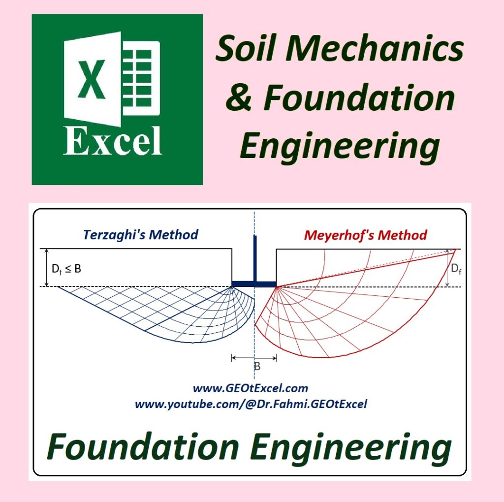
Three types of failure of soil support beneath the foundations have been recognized, depending upon the deformations associated with the load and the extent of development of failure surface.
They are: a) general shear failure, b) local shear failure and c) punching shear. The choice of which method of analysis is best suited in a given situation is difficult to make, because only limited test data are available on full sized foundations to verify the reliability of the computed bearing capacity. However, guidelines given in relevant clauses may be used for guidance. Wherever possible bearing capacity calculations shall be made on the basis of shear strength parameters ϕ and c obtained from appropriate shear tests [see IS: 2720 (Parts XI and XIII)*] or from plate load test results as given in IS: 1888-1981 or from static cone penetration resistance qc obtained from static cone penetration test as given in IS: 4968 (Part III)-1976.
General Shear Failure
Local Shear Failure
Calculation for Cohesive-Frictional, Cohesionless and Cohesive Soils
5.0.1 Effect of Eccentricity
a) Single Eccentricity — If the load has an eccentricity , with respect to the centroid of the foundation in only one direction, then the dimension of the footing in the direction of eccentricity shall be reduced by a length equal to . The modified dimension shall be used in the bearing capacity equation and in determining the effective area of the footing in resisting the load.
b) Double Eccentricity — If the load has double eccentricity with respect to the centroid of the footing then the effective dimensions of the footing to be used in determining the bearing capacity as well as in computing the effective area of the footing in resisting the load shall be determined as given below: A′=L′×B′
5.1 Soils with Cohesion and Angle of Shearing Resistance:
5.1.1 Strip Footings:
The following formulae shall be used for calculating ultimate net bearing capacity in the case of strip footings:
a) In case of general shear failure
b) In case of local shear failure
The values of and may be obtained from Table 1.
TABLE 1: BEARING CAPACITY FACTORS
(Degrees)
0
5.14
1.00
0.00
5
6.49
1.57
0.45
10
8.35
2.47
1.22
15
10.98
3.94
2.65
20
14.83
6.40
5.39
25
20.72
10.66
10.88
30
30.14
18.40
22.40
35
46.12
33.30
48.03
40
75.31
64.20
109.41
45
138.88
134.88
271.76
50
266.89
319.07
762.89
Notes:
For obtaining values of , and , calculate .
Read , , and from the Table corresponding to the value of instead of which are values of , , respectively.
5.1.2 Modified Ultimate Net Bearing Capacity Formula:
The ultimate net bearing capacity obtained in 5.1.1 for strip footing shall be modified to take into account, the shape of the footing, inclination of loading, depth of embedment and effect of water table.
The modified bearing capacity formulae are given as under:
a) In case of general shear failure
b) In case of local shear failure
5.1.2.1 The shape factors shall be as given in Table 2.
TABLE 2: SHAPE FACTORS
Shape of Base
i) Continuous strip
1.00
1.00
1.00
ii) Rectangle
iii) Square
1.3
1.2
0.8
iv) Circle
1.3
1.2
0.6
5.1.2.2 The depth factors shall be as under:
Note — The correction is to be applied only when back filling is done with proper compaction.
5.1.2.3 The inclination factor shall be as under:
GEOtExcel: Shape, Depth and Inclination FACTORS: Continuous Strip
GEOtExcel: Shape, Depth and Inclination FACTORS: Circle
GEOtExcel: Shape, Depth and Inclination FACTORS: Rectangle
GEOtExcel: Shape, Depth and Inclination FACTORS: Square
5.1.2.4 Effect of water table
a) If the water table is likely to permanently remain at or below a depth of beneath the ground level surrounding the footing then .
b) If the water table is located at a depth or likely to rise to the base of the footing or above then the value of shall be taken as 0.5.
c) If the water table is likely to permanently get located at depth , then the value of be obtained by linear interpolation.
5.2 Cohesionless Soil ( c=0 )
The ultimate net bearing capacity shall be calculated as given in 5.2.1 and 5.2.2.
5.2.1 Based on Relative Density
The formulae given in 5.1.1 and 5.1.2 shall be used, together with relevant shear strength parameter.
5.2.1.1 The relative density as given in Table 3 shall be used as a guide to determine the method of analysis.
TABLE 3 METHOD OF ANALYSIS BASED ON RELATIVE DENSITY
i)
Greater than 70 percent
Less than 0.55
Dense
General shear
ii)
Less than 20 percent
Greater than 0.75
Loose
Local shear (as well as punching shear)
iii)
20 to 70 percent
0.55 to 0.75
Medium
Interpolate between i) and ii)
5.2.2 Based on Standard Penetration Resistance Value
The standard penetration resistance shall be determined as per IS: 2131-1981* at a number of selected points at intervals of 75 cm in the vertical direction or change of strata if it takes place earlier and the average value beneath each point shall be determined between the level of the base of the footing and the depth equal to 1.5 to 2 times the width of foundation. In computing the value, any individual value more than 50 percent of the average calculated shall be neglected, and average re-calculated (the values for all loose seams shall however be included).
5.2.2.1 The ultimate net bearing capacity shall be calculated from the following formula (covering effect of other factors as mentioned in 5.1.2):
Where q may be read from Fig. 1, may be read from Table 1, and may be obtained as in 5.1.
SPT-Derived ϕ
The methods in this section follow IS 6403:1981, but for modern limitations and advanced correlations, refer to the GEOtExcel Technical Critique & Recommendations section at the end of this post.
5.2.3 Method Based on Cone Penetration Test (CPT) for Cohesionless Soil
The static cone point resistance ‘qc’ shall be determined as per IS: 4968 (Part III)-1976† at number of selected points at intervals of 10 to 15 cm. The observed values shall be corrected for the dead weight of sounding rods. Then the average value at each one of the location shall be determined between the level of the base of the footing and the depth equal to BB to 2 times the width of the footing. The average of the static cone point resistance values shall be determined for each one of the location and minimum of the average values shall be used in the design. The ultimate bearing capacity of shallow strip footings on cohesionless soil deposits shall be determined from Fig. 2.
The methods in this section follow IS 6403:1981, but for modern limitations and advanced correlations, refer to the GEOtExcel Technical Critique & Recommendations section at the end of this post.
5.3 Cohesive Soil (when )
5.3.1 Homogeneous Layer
5.3.1.1 The net ultimate bearing capacity immediately after construction on fairly saturated homogeneous cohesive soils shall be calculated from following formula:
where
The value of shall be obtained from unconfined compressive strength test. Alternatively, it can also be derived from static cone test (see 5.3.1.2). The values of , and may be obtained as in 5.1. If the shear strength for a depth of beneath the foundation does not depart from the average by more than 50 percent, the average may be used in the calculation.
5.3.1.2 Alternately, cohesion shall be determined from the static cone point resistance using the empirical relationship shown below:
Soil Type
Point Resistance Values (qc) kgf/cm²
Range of Undrained Cohesion (kgf/cm²)
Normally consolidated clay
qc<20
to
Over consolidated clays
to
The methods in this section follow IS 6403:1981, but for modern limitations and advanced correlations, refer to the GEOtExcel Technical Critique & Recommendations section at the end of this post.
5.3.2 Two Layered System
In the case of two layered cohesive soil system which do not exhibit marked anisotropy the ultimate net bearing capacity of a strip footing can be calculated by using the formula given below:
where may be obtained from Fig. 3.
The methods in this section follow IS 6403:1981, but for modern limitations and advanced correlations, refer to the GEOtExcel Technical Critique & Recommendations section at the end of this post.
5.3.3 Desiccated Soil
In the case of desiccated cohesive soils, the undrained cohesion is likely to decrease along with depth and is likely to get stabilized at some depth below ground level, around 3.5 m, if other factors do not influence. If a plot of undrained cohesion values as shown in Fig. 4 is obtained, and where the pressure bulb falls within the desiccated top soil, the ultimate net bearing capacity shall be obtained with the assumption of cylindrical failure surface from Table 4.
The methods in this section follow IS 6403:1981, but for modern limitations and advanced correlations, refer to the GEOtExcel Technical Critique & Recommendations section at the end of this post.
6. ALLOWABLE BEARING CAPACITY
6.1 The allowable bearing capacity shall be taken as either of the following, whichever is less:
a) Net ultimate bearing capacity divided by a suitable factor of safety (net safe bearing capacity).
b) The net soil pressure that can be imposed on the base without the settlement exceeding the permissible values as given in IS: 1904-1978 (safe bearing pressure).
6.1.1 Safe Bearing Pressure
The permissible settlements for different types of soil formations are specified in IS: 1904-1978*. The methods for calculations of settlements for assumed pressure from standard penetration resistance are specified in IS: 8009 (Part I)-1976†; by calculating the settlements for two or three probable soil pressures and interpolating, the net soil pressure for permissible settlement may be estimated. This safe bearing pressure can also be calculated based on plate load test (see IS: 1888-1982).
Beyond IS 6403: Technical Critique & Recommendations for Bearing Capacity Estimation by GEOtExcel
GEOtExcel Advisory Note: While IS 6403:1981 is a long-standing standard for shallow foundation design, its empirical correlations were developed several decades ago. Modern geotechnical practice, including Eurocode 7 and advanced literature by Das and Bowles, offers more refined methods. Users are advised to consider the following critiques when using the IS 6403:
Comparison Table: IS 6403 vs. Modern Geotechnical Practice
Feature / Clause
IS 6403:1981 Approach
Recommendation
SPT in Cohesionless Soil (Cl. 5.2.2)
Uses N values for ϕ from a simple chart (Fig. 1).
Requires explicit N60 (energy) and N1(60) (overburden) corrections.
CPT in Sands (Cl. 5.2.3)
Uses raw average qc with Figure 2 curves.
Requires normalizing qc for effective stress or correlating to ϕ for stress-dependent analysis.
CPT in Clays (Cl. 5.3.1.2)
Simple ratios like qc/15 or qc/18 to estimate cu.
Uses cu=(qc−σv0)/Nkt, accounting for total overburden stress (σv0).
Layered Soils (Cl. 5.3.2)
Relies on static charts (Fig. 3) for Nc factors.
Recommends Punching Shear analysis to model stress distribution through stiff-over-soft layers.
Desiccated Soils (Cl. 5.3.3)
Assumes a fixed linear reduction of cohesion with depth.
Uses Unsaturated Soil Mechanics; warns of strength loss (collapse) upon saturation.
1. Internal Friction Angle (ϕ) from SPT (Fig. 1)
IS 6403 Limitation: The code provides a direct relationship between the N value and ϕ in Fig. 1. Although it mentions “Corrected N value”, it lacks explicit instructions for essential modern corrections like N60 (energy correction) and N1(60) (overburden pressure correction).
Modern Recommendation: Following Das (2019) design engineers should first apply energy and stress-level corrections to the field N value before estimating ϕ. Relying on uncorrected or partially corrected values may lead to overestimating the soil’s shear strength.
= 100 kPa
Recommended Correlations:
Reference
Applicability
Formula
Wolff (1989)
Sands & non-plastic silts
Hatanaka & Uchida (1996)
Clean sands
Kulhawy & Mayne (1990)
Sands & gravelly sands
2. Cohesionless Soils based on CPT (Clause 5.2.3 & Fig. 2)
IS 6403 Limitation: The standard calculates bearing capacity directly from the average qc value using the empirical curves in Figure 2.
Modern Recommendation: Modern practice emphasizes that qc is highly dependent on effective overburden pressure. It is recommended to normalize qc values for stress levels or use them to derive the friction angle (ϕ) for a more robust analysis.
Comprehensive CPT-Based Table for IS 6403 Bearing Capacity
Method / Reference
Formula / Procedure
Application & Technical Notes
Lunne et al. (1997)
Effective Friction Angle (ϕ′)
Verification: Suitable for Cohesionless Soils
= vertical effective stress at test depth
Robertson & Campanella (1983)
Empirical Friction Angle (ϕ′)
Verification: Suitable for granular soils and medium sands to confirm ϕ′ values.
= vertical effective stress at test depth
Eslami-Fellenius (CPTu)
Step 1:
Step 2:
Step 3: Step 4:
a = net cone area ratio (0.7 to 0.85) = corrected cone resistance = pore pressure behind cone Influence zone = 2B.
Furthermore, settlement—rather than shear—often governs design in sands, which requires more advanced CPT-based settlement analysis (e.g., Schmertmann’s method).
3. Undrained Cohesion (cu) from CPT (Clause 5.3.1.2)
IS 6403 Limitation: The code uses simple ratios (e.g., qc/15 or qc/18) to estimate cohesion from cone resistance. This approach ignores the total overburden stress at the test depth.
Modern Recommendation:Eurocode 7 suggests the use of the Nkt factor (Cone Factor) where cu=(qc−σv0)/Nkt. This method accounts for the in-situ stress state (σv0), providing a far more accurate representation of soil strength, especially at greater depths:
(Where σᵥ₀ is the total overburden stress and Nkt is typically 10–20.)
Typical Values by Soil Type
Soil Type / Condition
Typical Range
Highly sensitive clays (e.g., quick clays)
8 – 12
Soft, normal clays
12 – 16
Firm to stiff clays
16 – 20
Eurocode 7 (default, no site calibration)
15
Overconsolidated clays (OCR > 2)
18 – 20
4. Two-Layered Cohesive Soil Systems (Fig. 3)
IS 6403 Limitation: The bearing capacity factors (Nc) in Fig. 3 are based on simplified charts. These do not fully capture the complex “Punching Shear” failure mechanism that occurs when a thin stiff crust overlies a soft clay layer.
Modern Recommendation: Approaches suggested by Das and Bowles analyze the distribution of stress through the top layer and the shearing resistance along the failure perimeter. For critical projects, numerical analysis or the punching shear theory is recommended over the static charts of IS 6403.
Modern Formula (Meyerhof & Hanna): For a stiff layer over a soft layer:
Term
Physical meaning
Unit
Ultimate bearing capacity of the two‑layer system
kPa
Ultimate bearing capacity of the underlying soft layer alone
kPa
Shearing resistance along the two vertical sides of the punched zone (adhesion)
kPa
Frictional resistance along the inclined failure surface within the stiff layer
kPa
Reduction due to the weight of the stiff layer pushing down on the soft layer
kPa
Ultimate bearing capacity of the top (stiff) layer alone (upper bound)
kPa
5. Desiccated & Fissured Soils (Clause 5.3.3)
IS 6403 Limitation: The standard assumes a linear reduction of cohesion with depth (Table 4 and Fig. 4). This is a highly empirical and simplified model for complex desiccated profiles.
Modern Recommendation: Modern practice utilizes Unsaturated Soil Mechanics. The strength of desiccated soils is primarily governed by Matric Suction, which varies seasonally with moisture content. Design engineers should be cautious of the “collapse” or “swelling” potential of these soils upon wetting, which the linear model in IS 6403 does not address.
Semi-Empirical Model (Vanapalli & Mohamed, 2013):
Term
Physical meaning
Unit
Ultimate bearing capacity of unsaturated soil
kPa
Effective cohesion (saturated condition)
kPa
Average matric suction over the influence zone
kPa
Degree of saturation
– (0 to 1)
Empirical pore size distribution parameter (typically 1–4)
Bishop’s parameter (depends on degree of saturation, )
–
Matric suction ()
kPa
Effective friction angle
degree
Bearing capacity factors (function of )
–
Depth correction factors (embedment effect)
–
Effective overburden pressure at footing base
kPa
Unit weight of soil
kN/m³
Footing width
m
Final Conclusion:
Users are encouraged to use GEOtExcel as a powerful tool for IS 6403 compliance but should supplement their designs with modern correlations for enhanced reliability and safety in complex soil conditions.
1️⃣ Ultimate Bearing Capacity Calculation – Academic Education Focus 2️⃣ Ultimate Bearing Capacity Calculation (Design) as per IS 6403 Code
☑️ [GEO-2026-IS6401-Design] & [GEO-2026-IS6401-Cocept] 📊 “Developed by GEOtExcel Co., Copyrighted.”
1️⃣ Effect of Water Table on the Bearing Capacity 2️⃣ Effect of Relative Density on the Bearing Capacity of Cohesion-less Soils 3️⃣ Effect of Eccentric Loading on the Bearing Capacity
GEOtExcel 2025-1 is now easier to access, fully secure, and permanently usable on your personal computer. With this version, GEOtExcel brings an Excel-based desktop application packed with essential tools for soil mechanics, foundation engineering, and geotechnical testing.
What’s New in GEOtExcel 2025-1?
Thanks to valuable user feedback, the delivery method of GEOtExcel has been improved. The 2025-1 version now offers:
1️⃣ Lifetime, Unlimited Access: Use it anytime on your personal computer. 2️⃣ No Restrictions: Save, print, and manage data locally without any limitations. 3️⃣ Offline Access: No need for an internet connection or cloud service to use GEOtExcel.
Important Note
The current GEOtExcel 2025-1 version is fully functional and permanently usable on the registered computer. (If future versions are released and you choose to upgrade, you’ll receive special discounts for existing users.)
How to Order GEOtExcel 2025
To begin the process of getting GEOtExcel 2025, follow these steps:
Subscribe to get the latest updates, lectures, and spreadsheets for soil mechanics, foundation engineering, and geotechnical testing. ➡️ Subscribe on YouTube
Foundation Engineering – Pile Frictional Resistance (Beta Method)
[GEO-2025-0105] – Developed by GEOtExcel Co.
This educational spreadsheet package provides a step-by-step solution for pile frictional resistance calculations using the Beta Method in foundation engineering. It helps in analyzing the frictional resistance of a concrete pile in sandy soil and understanding the effects of varying parameters such as pile length, diameter, and friction angle.
Problem Overview:
A concrete pile with:
Length (L) = 10m
Diameter (D) = 0.5m
Soil Friction Angle (φ’) = 20°
Eccentricity (e) = 0.5
Pile-Soil Friction Angle = (2/3 φ’)
Steps Covered:
A) Calculate the frictional resistance (Qs) using the Beta Method. B) Analyze the effect of varying L (10-15m), D (0.5-1m), and φ (20°-30°) on the frictional resistance. C) Evaluate the impact of groundwater level ossification on the pile frictional resistance.
What’s Included:
3 Professional Spreadsheets designed for analyzing pile frictional resistance using the Beta Method.
Comprehensive step-by-step solutions for all variables affecting pile frictional resistance.
Spreadsheets Included:
Start Sheet: Introduction to the pile frictional resistance problem and parameters.
Problem01: Detailed Foundation Engineering Problem with corresponding solution approach using GEOtExcel.
Qs-Solution: Pile Frictional Resistance (Qs) Calculation using the Beta Method.
Features and Benefits:
Complete Analysis: This package includes comprehensive steps for calculating pile frictional resistance under different loading conditions and soil parameters.
Educational Use: Ideal for students and professionals in foundation engineering and geotechnical engineering.
Real-world Problem Solving: Provides a practical solution to a common engineering challenge in foundation design.
Why Choose GEOtExcel:
Expert-Developed: Created by Dr. Ahmad Fahmi, an expert in foundation engineering and soil mechanics.
Educational & Professional Quality: Suitable for both classroom learning and professional practice.
User-Friendly Format: Easy-to-use Excel spreadsheets designed for efficient problem-solving in geotechnical and foundation engineering.
Part of the GEOtExcel 2025-1 Collection
12 Groups of spreadsheets
50 Files covering various geotechnical topics
470+ Spreadsheets
Commercially Licensed: Full access for professionals and educational use
Assistant Professor, Geotechnical Engineering, University of Bonab Dr. Fahmi is a leading expert in soil mechanics, foundation engineering, and geotechnical testing, dedicated to providing high-quality educational tools for professionals and students.
📌 Stay Updated:
Subscribe to get access to the latest soil mechanics, foundation engineering, and geotechnical testing lectures on YouTube: ➡️ Subscribe on YouTube
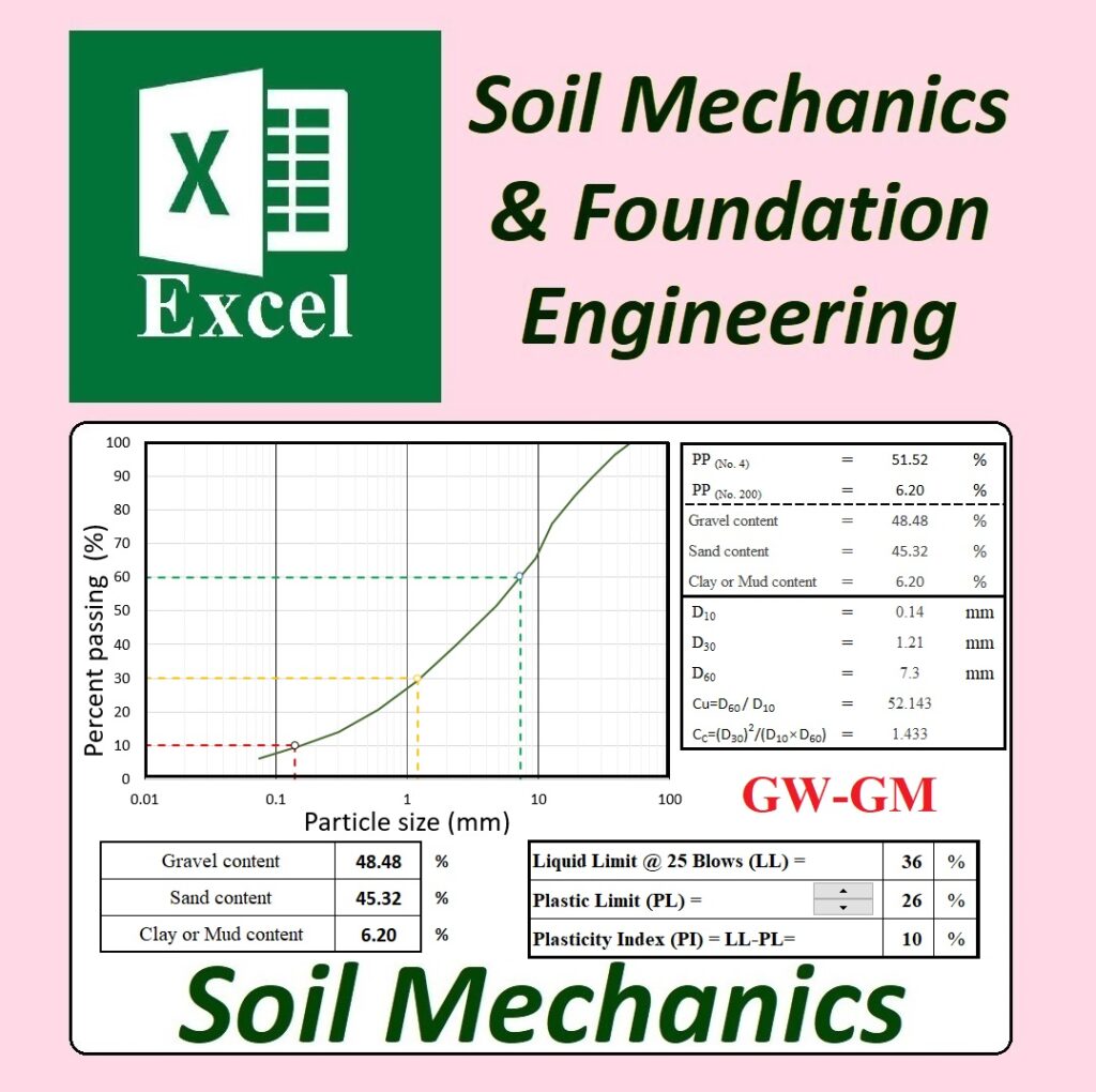
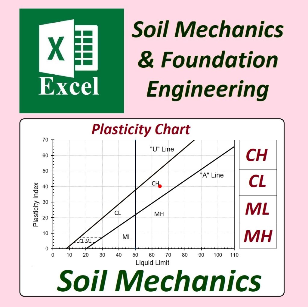
Soil Mechanics – Unified Soil Classification System & Hydrometer Analysis for Fat Clay (CH)
[GEO-2025-0115] – Developed by GEOtExcel Co.
This professional spreadsheet package provides a detailed solution for Soil Mechanics focusing on Fat Clay (CH) using the Unified Soil Classification System (USCS) and Hydrometer Analysis.
What’s Included:
8 Professional Spreadsheets covering soil classification, sieve, and hydrometer analysis for Fat Clay (CH).
Detailed Breakdown:
[GEO-2025-0115]: 1) Start Sheet: Introduction to Unified Soil Classification System & Hydrometer Analysis for Fat Clay (CH). 2) DATA: Soil Classification data for Fat Clay (USCS). 3) USCS: Excel Spreadsheet for Unified Soil Classification System (USCS). 4) Sieve: Sieve Analysis for Fat Clay. 5) Hydrometer: Hydrometer Analysis for Fat Clay. 6) Table 1: Hydrometer 152H – Table1 7) Table 1-Full: Full data for Hydrometer 152H – Table1 8) Table 2: Hydrometer 152H – Table3 9) Table 2-Full: Full data for Hydrometer 152H – Table2 10) Table 3: Hydrometer 152H – Table1 11) Table 3-Full: Full data for Hydrometer 152H – Table3
Features and Benefits:
Comprehensive Soil Classification: Covers the USCS system and Hydrometer analysis for Fat Clay (CH), including sieve analysis.
Professional and Educational Use: Aimed at students and professionals in soil mechanics and geotechnical engineering.
Detailed Spreadsheets: The package includes 8 detailed spreadsheets, ideal for practical use in laboratory settings.
Complete Hydrometer Analysis: Includes detailed tables and hydrometer calculations, providing valuable insights for soil testing and classification.
Why Choose GEOtExcel:
Educational & Professional-Grade: These spreadsheets offer a detailed approach to soil classification and analysis, suitable for both educational and professional use.
Comprehensive & User-Friendly: The easy-to-use format ensures users can perform detailed soil tests and obtain reliable results efficiently.
Expert-Developed: Created by Dr. Ahmad Fahmi, an expert in soil mechanics and geotechnical engineering.
📦 Part of the GEOtExcel 2025-1 Collection
12 Groups of spreadsheets
50 Files for soil mechanics and foundation engineering
470+ Spreadsheets
Secure Access: Easily downloadable and usable on your computer
Commercially Licensed: Full access for professionals and educational use
Assistant Professor, Geotechnical Engineering, University of Bonab Dr. Fahmi is a leading expert in soil mechanics, foundation engineering, and geotechnical testing, dedicated to providing high-quality educational tools for professionals and students.
📌 Stay Updated:
Subscribe to get access to the latest soil mechanics, foundation engineering, and geotechnical testing lectures on YouTube: ➡️ Subscribe on YouTube
[GEO-2025-0109], [GEO-2025-0110], [GEO-2025-0111] – Developed by GEOtExcel Co.
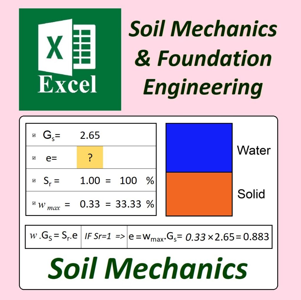
This comprehensive product includes 17 professional spreadsheets that help solve Soil Phase Relationships problems in Soil Mechanics. The spreadsheets cover Problem02, Problem03, & Problem04 in detail with a step-by-step approach, ensuring a thorough understanding of the concepts.
What’s Included:
[GEO-2025-0109]:7 Spreadsheets for Problem02, including detailed steps for solving the phase relationships.
[GEO-2025-0110]:6 Spreadsheets for Problem03, covering calculations and key principles in soil mechanics.
[GEO-2025-0111]:4 Spreadsheets for Problem04, designed to aid in comprehensive soil phase analysis and understanding.
Features and Benefits:
Step-by-Step Solutions: Each problem is solved with clear, structured steps to enhance learning and application.
Educational-Oriented: Ideal for students and professionals alike, these spreadsheets provide valuable insights and practice.
Comprehensive Coverage: From calculation of soil parameters to soil classification, the product covers all essential soil phase relationships in great detail.
Practical Applications: Designed for use in real-world soil mechanics problems and foundation design.
Why Choose GEOtExcel:
Complete Package: A total of 17 professional spreadsheets designed specifically for soil mechanics and phase relationships.
Trusted by Professionals: Developed by Dr. Ahmad Fahmi, an expert in Geotechnical Engineering.
Educational Focus: Aimed at enhancing your understanding of complex soil behavior and mechanics through practical and structured solutions.
📦 Part of the GEOtExcel 2025-1 Collection
12 Groups of spreadsheets
50 Files for soil mechanics and foundation engineering
470+ Spreadsheets
Secure Access: Easily downloadable and usable on your computer
Commercially Licensed: Full access for professionals and educational use
Assistant Professor, Geotechnical Engineering, University of Bonab Dr. Fahmi is a leading expert in soil mechanics, foundation engineering, and geotechnical testing, dedicated to providing high-quality educational tools for professionals and students.
📌 Stay Updated:
Subscribe to get access to the latest soil mechanics, foundation engineering, and geotechnical testing lectures on YouTube: ➡️ Subscribe on YouTube
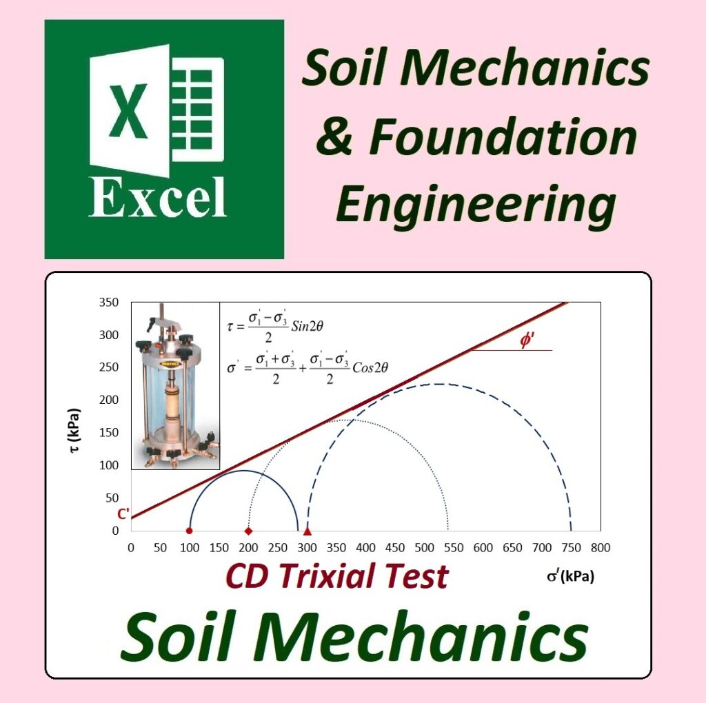
Advanced Soil Mechanics – Critical State Mechanics (MCC) Model | CU Triaxial Test
[GEO-2025-0140] – By Dr. Ahmad Fahmi
This advanced Geotechnical Excel Spreadsheet for Critical State Mechanics (MCC Model) is designed for CU Triaxial Tests in soil mechanics. It allows classification of soil into three categories:
NC – Normally Consolidated Clay
LOC – Lightly Over-Consolidated Clay
HOC – Highly Over-Consolidated Clay
The spreadsheet provides a professional tool for analyzing soil behaviors under different consolidation states, essential for advanced geotechnical engineering and foundation design.
What’s Included in the Product:
[GEO-2025-0140]: Includes 7 Professional Spreadsheets for soil classification based on the Modified Cam Clay (MCC) Model.
Start Sheet: Introduction and Overview.
MCC-CU Sheet: Main Super Sheet for Critical State Mechanics and CU Triaxial Test.
Calculation Sheets (Cal1-Cal5): For performing the detailed calculations required for soil classification under MCC.
Applications in Soil Mechanics and Geotechnical Engineering:
Critical State Mechanics (MCC Model): Used to understand the soil behavior under varying stress states.
CU Triaxial Test: Important for testing soil in consolidated undrained conditions.
Soil Classification: The tool classifies clay into normally consolidated, lightly over-consolidated, and highly over-consolidated based on the MCC Model.
Geotechnical Engineers: Essential for soil stability, foundation analysis, and earthworks.
Educational Use: Suitable for students and professors in advanced soil mechanics courses.
📦 Part of Geotechnical Excel Spreadsheets 2025-1 Collection
This product is part of the Geotechnical Excel Spreadsheets (2025-1) suite, featuring:
12 groups of spreadsheets
50 files for various soil mechanics and foundation engineering calculations
470+ spreadsheets
Secure and permanent access to all files on your computer
Assistant Professor, Geotechnical Engineering, University of Bonab Dr. Fahmi specializes in applying Excel-based solutions for soil mechanics, foundation engineering, and geotechnical testing.
[GEO-2025-0116], [GEO-2025-0117], [GEO-2025-0118] – By Dr. Ahmad Fahmi
We are excited to present the Soil Classification (USCS) tools in Geotechnical Excel Spreadsheets. This product includes 44 spreadsheets, offering a comprehensive solution for soil classification using the Unified Soil Classification System (USCS). The package includes various sections for comparing different soil classification systems, Fuller’s comparison, and analysis of poorly graded soils.
This tool is designed for geotechnical engineers, students, and soil mechanics professionals who are working with soil classification systems, especially focusing on the USCS.
What’s Included in the 44 Spreadsheets?
[GEO-2025-0116]: Comparison
20 Spreadsheets covering the USCS classification system, with detailed soil property analysis.
[GEO-2025-0117]: Comparison with Fuller
14 Spreadsheets offering a comparison between USCS and Fuller’s Classification.
[GEO-2025-0118]: Poorly Graded Soils
10 Spreadsheets focusing on the classification and analysis of poorly graded soils using the USCS.
Applications in Soil Mechanics and Geotechnical Engineering:
Unified Soil Classification System (USCS): Ideal for classifying soils based on particle size and plasticity characteristics.
Geotechnical Engineers: A useful tool for foundation design, soil testing, and soil analysis.
Educational Use: Great for soil mechanics students and professors to demonstrate soil classification methods.
Comparison Analysis: Includes Fuller’s Classification comparison, which is essential for understanding soil behavior in various construction contexts.
Advanced Soil Analysis: Provides tools for the analysis of poorly graded soils, an important factor in foundation design and soil stabilization.
📦 Part of Geotechnical Excel Spreadsheets 2025-1 Collection
This product is part of the Geotechnical Excel Spreadsheets (2025-1) suite, featuring:
12 groups of spreadsheets
50 files for various soil mechanics and foundation engineering calculations
470+ spreadsheets
Secure and permanent access to all files on your computer
Assistant Professor, Geotechnical Engineering, University of Bonab Dr. Fahmi specializes in applying Excel-based solutions for soil mechanics, foundation engineering, and geotechnical testing.
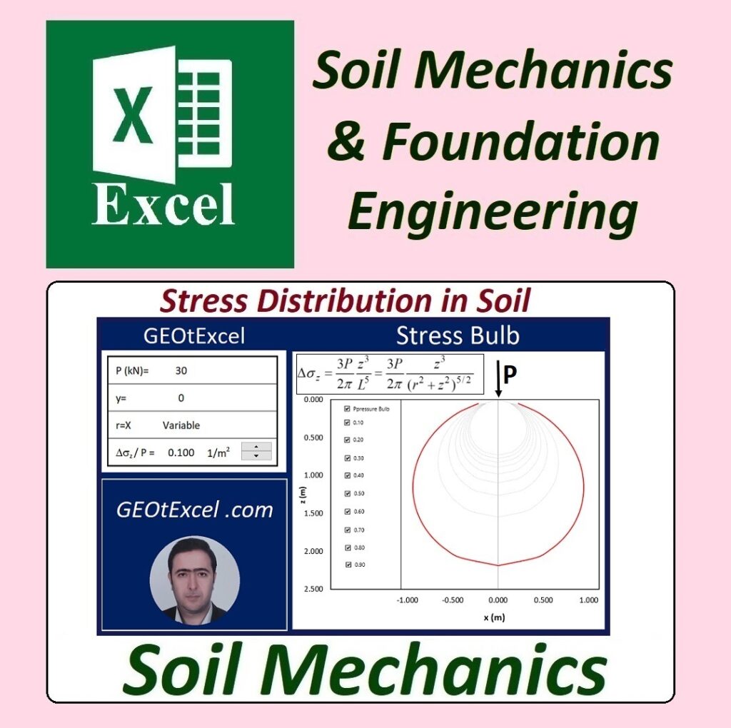
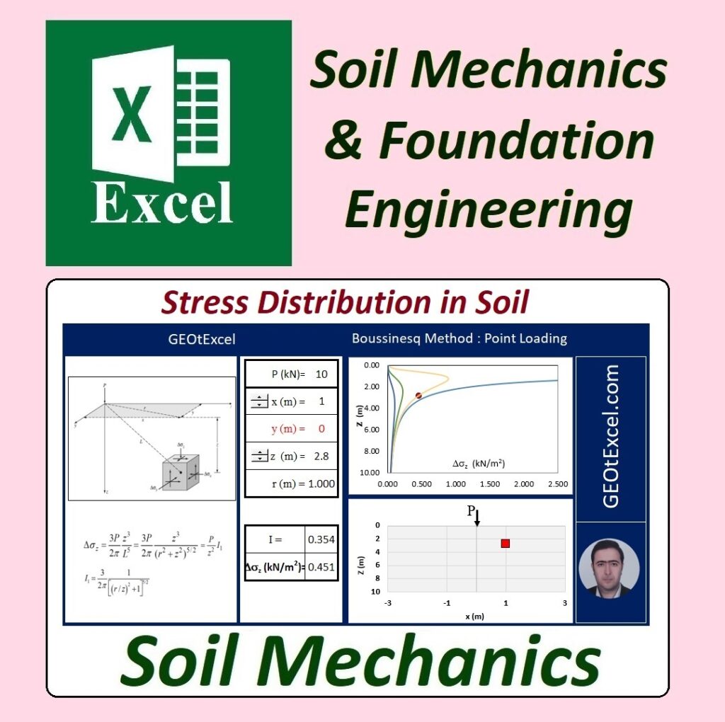
Soil Mechanics – Stress Distribution in Soil Using Newmark Method
[GEO-2025-0129 A&B] – By Dr. Ahmad Fahmi
We are pleased to present the Stress Distribution in Soil analysis tool using the Newmark Method with Geotechnical Excel Spreadsheets. This advanced product includes 22 spreadsheets, which provide a comprehensive solution for calculating the stress distribution in soils based on the Newmark method.
This product is designed for geotechnical engineers and soil mechanics students working on foundation design, soil analysis, and stress distribution. Whether you are analyzing the vertical stress distribution in soil or studying soil behavior under varying conditions, these spreadsheets will help you perform precise calculations.
What’s Included in the 22 Spreadsheets?
[GEO-2025-0129-A]:
Start Sheet: Introduction to the Newmark Method for stress distribution.
Main Super Sheet: Stress Distribution in Soil using the Newmark Method.
Calculation Sheets: Detailed spreadsheets for calculations based on the Newmark Method.
[GEO-2025-0129-B]:
Additional Spreadsheets for extended calculations and analysis.
More comprehensive breakdowns for stress distribution.
Applications in Soil Mechanics and Foundation Engineering:
Newmark Method: Use the Newmark Method for stress distribution calculations in soil mechanics.
Soil Behavior Analysis: Analyze the effect of external loads on soil using stress distribution models.
Geotechnical Engineers: Ideal for professionals working on shallow foundations and soil load analysis.
Educational Use: A great tool for students and professors in soil mechanics and geotechnical engineering courses.
Detailed Analysis: Includes multiple calculation options to accurately model stress distribution in different soil types.
📦 Part of Geotechnical Excel Spreadsheets 2025-1 Collection
This product is part of the Geotechnical Excel Spreadsheets (2025-1) suite, featuring:
12 groups of spreadsheets
50 files for various soil mechanics and foundation engineering calculations
470+ spreadsheets
Secure and permanent access to all files on your computer
Assistant Professor, Geotechnical Engineering, University of Bonab Dr. Fahmi specializes in applying Excel-based solutions for soil mechanics, foundation engineering, and geotechnical testing.
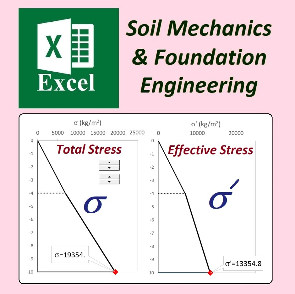
Soil Mechanics – Effect of Surcharge on Effective Stress
[GEO-2025-0125] – By Dr. Ahmad Fahmi
Introducing the comprehensive Excel Spreadsheets for analyzing the Effect of Surcharge on Effective Stress in soil mechanics. This product, developed by GEOtExcel Co., includes 24 spreadsheets designed to provide accurate calculations of effective stress when surcharge loads are applied to shallow foundations. The package includes two layouts (Layout 1 and Layout 2) for flexibility in analysis and application.
These spreadsheets are ideal for geotechnical engineers and students working on projects related to foundation design, soil mechanics, and surcharge effects. Whether you’re analyzing shallow foundations or soil behavior under surcharge load, these tools will help you calculate effective stress with ease.
What’s Included in the 24 Spreadsheets?
Start Sheet: Overview of the Effect of Surcharge on Effective Stress calculations.
Surcharge Main Super Sheet: Core sheet for analyzing the effect of surcharge on effective stress (kg/m²).
Calculation Spreadsheets: A series of 12 spreadsheets in both Layout 1 and Layout 2 for step-by-step calculations.
Applications in Soil Mechanics and Foundation Engineering:
Effective Stress Calculation: Calculate effective stress under surcharge loads with two layouts for flexibility and accuracy.
Foundation Design: Analyze the effect of surcharge on shallow foundations and soil behavior.
Practical Tool: Ideal for geotechnical engineers involved in soil testing and foundation design.
Educational Use: A great resource for students and professors studying soil mechanics and geotechnical engineering.
Advanced Analysis: Comprehensive tools for soil mechanics involving shallow foundation and surcharge load analysis.
📦 Part of Geotechnical Excel Spreadsheets 2025-1 Collection
This product is part of the Geotechnical Excel Spreadsheets (2025-1) suite, featuring:
12 groups of spreadsheets
50 files for various soil mechanics and foundation engineering calculations
470+ spreadsheets
Secure and permanent access to all files on your computer
Assistant Professor, Geotechnical Engineering, University of Bonab Dr. Fahmi specializes in applying Excel-based solutions for soil mechanics, foundation engineering, and geotechnical testing.